
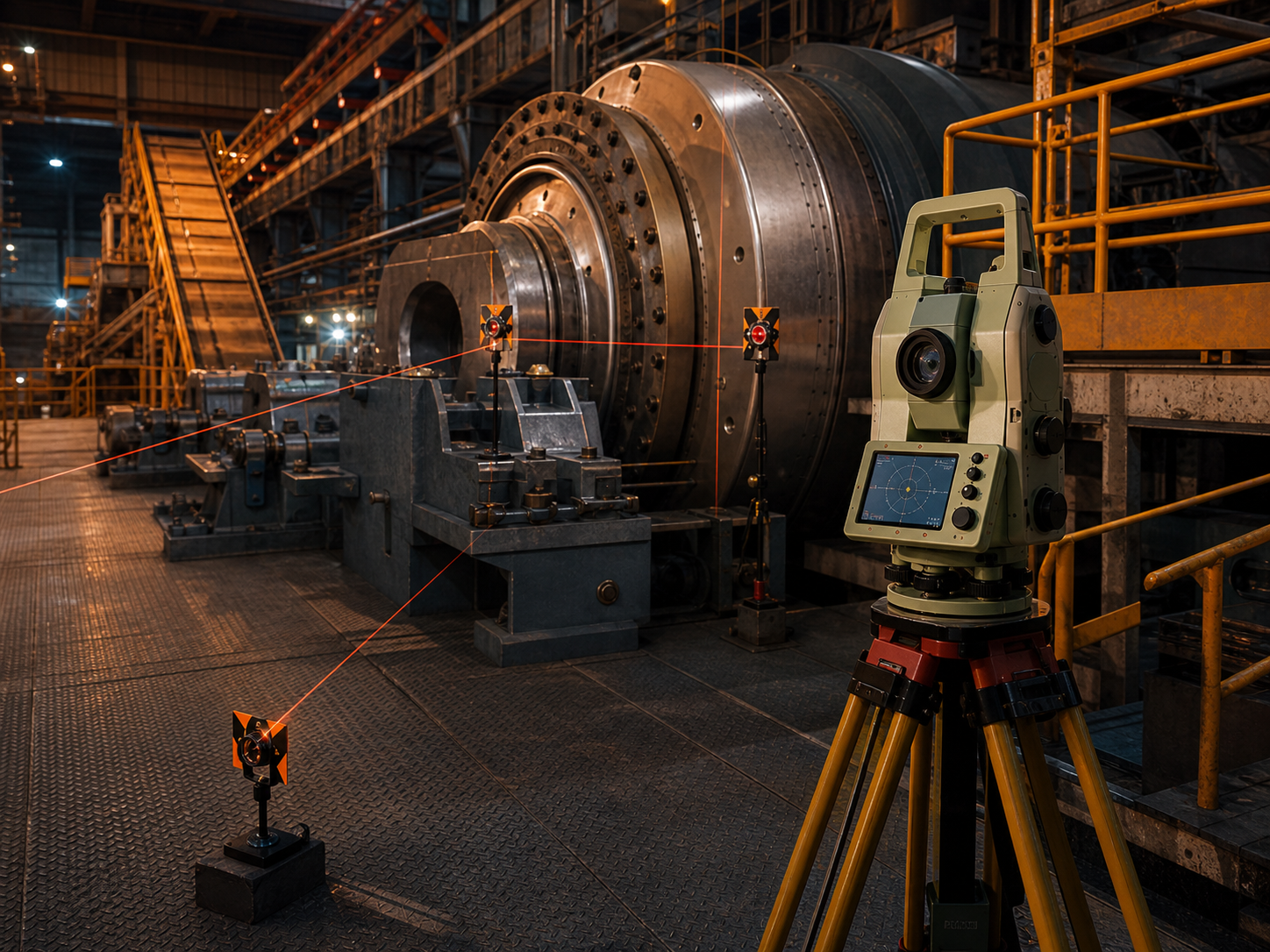
Dimensional control surveying is the discipline of measuring fabricated or installed steel, plant and structures against the design model using a single surveyed datum, so that accumulated error is found and corrected before it is welded, bolted or grouted into place. It is what stops six "in-tolerance" blocks stacking into an out-of-tolerance hull, or four anchor-bolt clusters that each look fine refusing to take a baseframe. Done properly it works to millimetre or sub-millimetre tolerances, ties every point to a stable least-squares network, and replaces "it won't quite line up" with a deviation value a fitter can act on. This guide covers the standards, equipment, tolerances, costs and a field-ready checklist for getting dimensional control right on Australian industrial projects.
Key takeaways
- Dimensional control measures the whole object against the design model on a common datum, not frame-to-frame with a tape — that reframing is what surfaces cumulative drift while it is still cheap to correct, on the jig or before grout, rather than after erection.
- The control network is the job: establish a stable local frame adjusted by least squares to better than ±0.5–1.0 mm relative before measuring anything, because a tracker or total station only ever sees part of a large structure from one setup and must leapfrog without losing the frame.
- Match the instrument to the volume — a Leica Absolute Tracker AT960 (±0.015 mm + 6 µm/m) for close-range fabrication and fit-up, a Leica MS60 MultiStation (0.5″, 1 mm + 1.5 ppm) or TS16 for plant-scale geometry, and an RTC360 or FARO Focus (~2 mm @ 10 m) for as-built capture against the model.
- There is no single "dimensional control standard" in Australia: work to the OEM model and project specification, with ISO 1101 geometric tolerancing principles and ISO/IEC 17025-traceable measurement making the result defensible — referencing AS/ISO equipment standards (e.g. AS 1418, ISO 1940/21940) only where the asset type prescribes them.
- Typical working tolerances span ±0.5 mm for machined interfaces and anchor bolts, ±1.5–3 mm for structural fit-up, and ±5 mm for general as-built handover — always subordinate to the manufacturer's or project specification.
- Budget AUD $2,500–4,500 per crew per day; a focused fit-up or anchor-bolt control survey runs $4,000–12,000, and a full module or block programme with control network and as-built reporting $15,000–40,000+ depending on size and access.
What dimensional control surveying actually is
A Western Australian shipyard erecting a 78 m patrol hull from six pre-fabricated blocks had two adjoining mid-body blocks each passing their own internal tape checks — yet the deck-edge sheer line was visibly not going to meet. A tracker-based dimensional control survey, run while both blocks were still on their jigs, measured each against the yard's 3D ship model and found the deviations ran the same way at the adjoining ends: 6.2 mm of cumulative drift across the planned butt joint, twice the yard's 3 mm working tolerance. Corrected on the jig by jacking and re-fairing, the seam then closed first time on the berth, eliminating a weld-out correction the yard had costed at over AUD $90,000.
That is dimensional control in one story. Where alignment surveying targets the rotation axis of running plant, dimensional control targets the geometry of fabricated and installed assets — hull blocks, structural modules, anchor-bolt patterns, baseframes, pipe spools, mating flanges and skid packages — comparing as-built steel to the design model. The deliverable is not a map; it is a colour-mapped deviation surface or a table of point-by-point offsets, and a clear instruction on what to move, shim, jack or re-machine.
The core principle is comparison against a model on a common datum. Traditional checking with tapes, plumb-bobs and optical levels is accurate locally but has a fatal blind spot: error accumulates. A 1 mm slip at one frame, another at the next, and the seam 14 m away is out by an amount no single measurement ever showed. Dimensional control asks "where is every control point relative to the design", not "is this point right relative to the last one" — and that is the entire value of the method.
Key point: the value is in catching accumulated error where correction is cheap. On the jig, before grout, before erection — not after the structure is locked together on the critical path.
Standards and datums that apply in Australia
Dimensional control is governed less by one prescriptive standard and more by a stack of geometric, equipment and survey references. The ones that recur on Australian projects:
| Reference | Scope | Relevance |
|---|---|---|
| ISO 1101 | Geometric product specification (GD&T) | Tolerancing principles where no asset-specific standard exists |
| ISO/IEC 17025 | Calibration and testing competence | Traceability of instrument calibration certificates |
| ISO 17123 series | Field procedures for testing survey instruments | Justifying instrument accuracy claims |
| AS 1418.1 / AS 1418.18 | Cranes, hoists; crane runways | Runway and rail tolerances where in scope |
| ISO 1940 / ISO 21940 | Rotor balancing quality | Context for rotating-plant interfaces |
| ICSM SP1 | Australian survey control network standard | Connecting to national datum when required |
| GDA2020 / MGA2020 | National horizontal datum and map grid | Site coordinates where the asset must tie to infrastructure |
| AHD | Australian Height Datum | Vertical referencing for level and grade work |
| CASA CASR Part 101 | Remotely piloted aircraft operations | Mandatory for any UAV/drone capture component |
Two practical notes. First, for pure asset geometry you usually do not want GDA2020. The frame that matters in shipbuilding is the vessel's build datum (centreline, baseline, frame zero); for a structural module it is the module's own setting-out grid. Importing MGA2020 grid scale factor and ppm error into a relative-millimetre fit-up only adds noise — connect to MGA2020/AHD only when the asset must be coordinated against site infrastructure, foundations or adjacent surveys. Second, where any part of the scope uses a drone — RGB or LiDAR capture of an inaccessible roof truss, stacker or gantry feeding the as-built — the operation must comply with CASA CASR Part 101: operator accreditation or RePL, an ReOC where applicable, and airspace approval, which matters constantly around ports, refineries and regional airfields.
Equipment and the accuracy it delivers
The instrument is the floor on your achievable tolerance — no processing recovers precision the hardware never captured. Choose by the volume and tolerance, not by what is in the ute.
| Equipment | Role in dimensional control | Stated accuracy |
|---|---|---|
| Leica Absolute Tracker AT960 | Close-range fabrication, fit-up, machined interfaces | ±0.015 mm + 6 µm/m |
| Leica MS60 MultiStation | Plant-scale geometry, datum transfer, monitoring | 0.5″ angle; 1 mm + 1.5 ppm |
| Leica TS16 total station | General dimensional control and setting-out | 1″ angle; 2 mm + 2 ppm |
| Trimble S-series total station | Equivalent general-purpose control | ~1″; 1 mm + 2 ppm |
| Leica RTC360 laser scanner | As-built capture, clash and clearance, ovality | ~2 mm @ 10 m |
| FARO Focus Premium scanner | As-built and structural capture | ~2 mm @ 10 m |
| DJI M350 RTK + payload | Aerial capture of inaccessible structure | Task dependent; CASR Part 101 |
For the tightest work — a machined mating face, an anchor-bolt cluster, hull or module fit-up — the AT960 laser tracker is the default; its accuracy is far inside any fabrication tolerance, so the limiting factor becomes the steel itself and the control network. For plant-scale geometry spanning tens of metres, the MS60 or TS16 carries a network the full length of a build hall or structure and lets a tracker leapfrog while every point stays in one frame. Laser scanning earns its place for full-surface as-built — model-to-scan deviation maps, clash checks before a tie-in, ovality on a vessel — but for a discrete control point a defined target observed directly remains more accurate and more traceable than fitting a surface to a point cloud.
The field method, step by step
- Plan and review. Pull the GA drawings, the 3D model or OEM data, the project tolerance specification, and any prior survey. Confirm the fabrication or installation sequence, access (scaffold, EWP, confined space) and permit requirements, and nominate the control points the client's engineers need measured.
- Establish control. Set permanent reference nests on stable structure — hall columns, floor monuments, foundation cast-ins — with clear intervisibility. Observe multiple rounds and run a least-squares adjustment, aiming for relative accuracy better than ±0.5–1.0 mm. This network is the spatial backbone; without it, six accurate part surveys are six measurements that will not stack.
- Reference the model. Bring the design model and its datum (build datum, setting-out grid, or GDA2020/AHD if required) into the same frame as the control network so comparison is direct, not arithmetic on a clipboard later.
- Capture as-built geometry. Measure the nominated control points — plate seams, bulkhead faces, flange centres, anchor-bolt tops, baseframe pads — leapfrogging the tracker or total station through the network as needed.
- Compare to design. Fit the as-built to the model and report deviation as a colour-mapped surface or a per-point offset table, not isolated measurements that hide cumulative error.
- Drive the correction live. Where the part is still adjustable, keep the instrument live during jacking, shimming or re-fairing so each movement is verified in real time rather than checked after tacking or grouting.
- Verify and re-measure. Confirm the corrected geometry against tolerance. Correction is iterative — a move at one support shifts adjacent points — so plan two to three check cycles on complex assemblies.
- Report. Issue deviation maps, tables and recommendations stating the instrument used, the network accuracy achieved, the datum or local frame, and the calibration traceability.
Watch out: never run dimensional control on construction-grade or consumer instruments. Millimetre and sub-millimetre tolerances demand survey-grade gear with current calibration traceable to national standards under ISO 17123 and ISO/IEC 17025.
Pre-survey field checklist
Hand this to the crew lead before mobilising. A clean checklist is the difference between a one-mobilisation job and an expensive second trip.
- Design model, GA drawings and project tolerance specification obtained
- Control points to be measured nominated and agreed with the client's engineers
- Datum decision made: build datum / local setting-out grid vs GDA2020/MGA2020 + AHD
- Fabrication or installation sequence confirmed so survey doesn't hold a welding/fitting crew
- Access plan confirmed (scaffold / EWP / confined space permits)
- Isolation, lock-out/tag-out and site induction completed
- Stable reference-nest locations identified with clear sightlines
- Instrument calibration certificates current (ISO/IEC 17025) and on site
- Target fittings (nests, prisms, tooling balls, bolt-top adaptors) available
- Deliverable format agreed: colour deviation map, offset table, or both
- Pass/fail tolerance acceptance criteria agreed in writing
- If UAV capture in scope: CASR Part 101 approvals and airspace clearance confirmed
Tolerances and indicative costs
Tolerances are always subordinate to the OEM or project specification — these are the typical working values Australian crews target when the spec is silent.
| Asset / parameter | Typical tolerance | Notes |
|---|---|---|
| Machined mating face / flange interface | ±0.1–0.5 mm | Tracker territory; AT960 |
| Anchor-bolt cluster position | ±0.5–1.0 mm | Before baseframe set / grout |
| Structural module fit-up | ±1.5–3 mm | Connection geometry vs model |
| Hull block butt joint | ±1.5–3 mm | Project working tolerance, ISO 1101 |
| Pipe spool / flange face-to-face | ±2–3 mm | Tie-in fit-up |
| Crane rail span / elevation | ±3 mm / ±2 mm per 10 m | AS 1418.1 / AS 1418.18 where in scope |
| General as-built handover | ±5 mm | Practical completion |
Costs depend on scope, location, access and schedule. Indicative AUD ranges for budgeting:
| Service | Indicative cost (AUD) | Typical duration |
|---|---|---|
| Crew day rate (instrument + surveyor) | $2,500–4,500 | per day |
| Anchor-bolt / baseframe control survey | $4,000–9,000 | 1–2 days |
| Fit-up guidance (live tracker) | $5,000–12,000 | 2–4 days |
| Structural module / block programme | $15,000–40,000+ | with control network + reporting |
| Laser-scan as-built (plant area) | $4,000–15,000 | 1–5 days |
| Model-to-scan deviation report | $2,000–6,000 | per area / deliverable |
Remote mobilisation to the Pilbara, the Bowen Basin or a WA shipyard, after-hours or shutdown-window work, and confined-space or working-at-heights requirements all push the upper end. For the full service scope and what each deliverable includes, see our mechanical surveys overview.
Common problems dimensional control catches
- Cumulative fit-up drift — small per-frame or per-connection slips that pass local checks yet stack into a joint, module mate or hull seam that will not close. Only a model-referenced survey surfaces it.
- Anchor-bolt cluster errors — bolt patterns set from a string line that look correct individually but won't accept the baseframe, found before grout when correction is a re-drill rather than a chipped-out foundation.
- Skid and module mating mismatch — two skids fabricated by different shops that each meet their own GA but don't present cleanly at the interface, caught against a common datum before craning.
- As-built vs model deviation — steel that has moved through welding distortion or thermal effects, mapped against the model so the deviation is visible and quantified, not guessed.
- Setting-out and foundation error — cast-in plates, pockets and pads out of position, exposed against a stable network before the structure that sits on them arrives.
Most of these are invisible to inspection and obvious to measurement. That is the entire case for dimensional control: you cannot correct what you have not measured against the model. Our mechanical surveys team builds the control network and reporting around exactly these failure modes.
Frequently asked questions
How is dimensional control different from a normal site survey?
A site survey positions things against a site or national grid (GDA2020/MGA2020, AHD) to the centimetre — boundaries, levels, earthworks. Dimensional control positions fabricated geometry against the design model to the millimetre or better, usually in the asset's own datum, and reports deviation as offsets or a colour map. Different tools, different tolerances, different deliverable: one tells you where the asset sits on the planet, the other tells you whether it will fit together.
Do we need a 3D model to use dimensional control?
It is the ideal input, because the whole method is comparison against design. Where a full model exists, ISS measures as-built control points and returns a model-to-as-built deviation surface. Where there is no model — only 2D GAs — we work from nominated control points and coordinate geometry, comparing measured positions to design dimensions. A model gives the richest output, but the discipline still applies without one.
Which instrument do we actually need — tracker or total station?
By volume and tolerance. A laser tracker (AT960) is for close-range, very tight work: machined faces, anchor-bolt clusters, fit-up to a fraction of a millimetre. A total station (MS60, TS16, Trimble S-series) is for plant-scale geometry over tens of metres and to carry the network a tracker leapfrogs along. Most module and block jobs use both — the total station for the hall-spanning network, the tracker for the close geometry.
Is there an Australian Standard for dimensional control tolerances?
No single prescriptive one. Unlike crane runways, which AS 1418.18 governs, fit-up and module tolerances come from the OEM model and project specification. ISS works to that specification, applies ISO 1101 geometric tolerancing principles, and uses ISO/IEC 17025-traceable measurement. The method and the traceability are what make a result defensible, not a single referenced clause.
When in the project should dimensional control happen?
As early as the geometry is measurable and still adjustable — on the jig before erection, before grout on anchor bolts, before craning on mating modules. The entire value is catching accumulated error where correction is cheap (jacking, shimming, re-drilling) rather than after the asset is welded or bolted onto the critical path. The earlier each part is measured against the model, the cheaper any correction is.
Talk to ISS
If you have a fabrication run, a module mate or an installation coming up, the cheapest move is to measure against the model before you commit the steel. Industrial Spatial Solutions delivers tracker- and total-station-based dimensional control for shipbuilders, fabricators, offshore-module yards, mining and processing clients across Australia — from our base in the Illawarra to WA shipyards, the Pilbara and the Bowen Basin — using Leica AT960, MS60, TS16 and RTC360 hardware, least-squares-adjusted control networks, and reports your fitters can act on the same shift. Call 0407 057 015 or contact us to scope your next dimensional control survey, or read more about our mechanical surveys capability.