
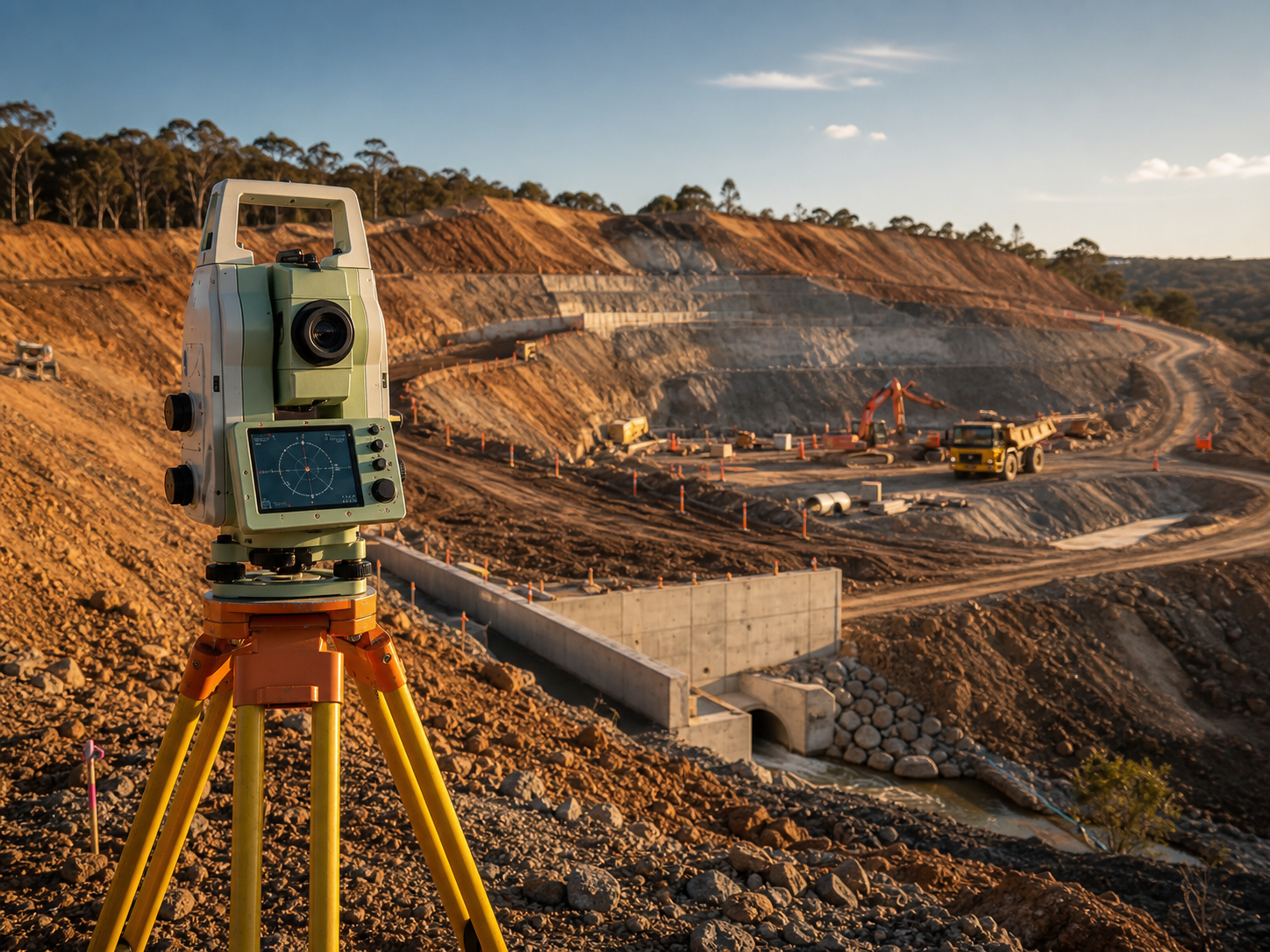
A survey control network is the framework of permanently marked, precisely coordinated points that every measurement on your project hangs off — set-out, levels, volumes, machine control, as-builts and monitoring all inherit its accuracy. Get the control right and a multi-year, multi-contractor job stays in one consistent coordinate system; get it wrong and the error is baked into everything downstream, usually invisible until it is expensive to fix. This guide explains how to specify, establish, verify and maintain an engineering control network in the Australian context — the right ICSM SP1 order, the correct GDA2020/MGA2020/AHD framework, the instruments that achieve each tolerance, and what it realistically costs.
Key takeaways
- Match the ICSM SP1 order to the task: Third Order (±50 mm H) for general earthworks and topo, Second Order (±15 mm) for building and plant set-out, First Order (±5 mm) for tunnel and major-structure work, Zero Order (±1 mm relative) for deformation monitoring and precision alignment. Over-specifying is just wasted money; under-specifying invalidates the work.
- Tie the network to GDA2020 horizontal in the correct MGA2020 zone and AHD for heights, with the combined scale factor stated in writing. GDA94 and GDA2020 differ by roughly 1.8 m — mixing them silently shifts the entire job.
- Build redundancy and hierarchy: primary control at 200-500 m on stable ground outside the works, secondary at 50-150 m for daily reference, tertiary as working set-out. A braced, closed network lets a least-squares adjustment detect blunders; an open traverse cannot.
- Choose the instrument to meet the spec, not the brand: GNSS (Leica GS18, Trimble R12i) for primary baselines and connection to AUSPOS/CORS, a Leica TS16 or MS60 MultiStation for terrestrial observation and densification, precise digital levelling with invar staves for AHD heights.
- Control is typically 5-10% of total survey cost but de-risks the whole programme. Budget roughly AUD $3,000-$8,000 for a small site, $8,000-$40,000 for medium-to-large sites, and $40,000-$100,000+ for major or monitoring-grade networks.
- Verify before you build on it: report achieved accuracy against independent checkpoints, not the software's optimistic internal residuals. For set-out, as-constructed and design surfaces tied to verified control, work with an engineering and civil surveyor.
What an engineering control network is — and why it controls everything
An engineering survey control network is a set of monumented points with rigorously determined coordinates (easting, northing and reduced level) in a defined datum, measured in a connected configuration so that errors can be detected and distributed. Every other survey activity — total-station set-out of a footing, RTK staking of a road centreline, a Leica RTC360 scan of a process module, a DJI M350 RTK stockpile flight — connects back to these points. The control is the single shared truth that makes today's work align with last year's and next year's.
The reason it matters so much is error propagation. If a primary mark is 30 mm out, every secondary point established from it inherits that 30 mm, every set-out point inherits it again, and the as-built that "proves" the work is wrong by the same amount while looking internally perfect. On a process plant or a bridge, a fixed coordinate offset of a few centimetres translates directly into clashes between steel and concrete, pipework that will not connect across a tie-in, or a conveyor that does not line up with the structure built to receive it. Control failures are rarely loud at the moment they occur; they surface as rework, claims and programme slip months later.
Three properties define a usable network: accuracy (known uncertainty relative to neighbours and, where needed, to the national framework), permanence (monuments that survive construction, plant and weather), and interconnection (each point tied to several others so a least-squares adjustment can find and isolate a bad observation).
Accuracy classes: choosing the right ICSM SP1 order
Australian control surveys are classified by ICSM SP1 (Standard for the Australian Survey Control Network) using positional uncertainty. The practical engineering shorthand maps to orders as follows.
| Order | Horizontal accuracy | Vertical accuracy | Typical engineering application |
|---|---|---|---|
| Zero Order | ±1 mm relative | ±0.5 mm relative | Deformation monitoring, mill/kiln precision alignment |
| First Order | ±5 mm | ±3 mm | Tunnel and shaft control, major structure monitoring |
| Second Order | ±15 mm | ±10 mm | Building set-out, mine primary control, plant steel |
| Third Order | ±50 mm | ±30 mm | Earthworks, road corridors, topographical survey |
The discipline is to specify the order against what the deliverable actually needs. Structural steel and process equipment that bolt together demand Second Order or tighter; a 200-hectare bulk-earthworks pad does not, and paying for ±5 mm control across it wastes both field time and money. Conversely, trying to align a SAG mill or set conveyor idlers off Third Order control guarantees a tolerance failure. State the required positional uncertainty in the survey brief and require the surveyor to confirm the proposed network geometry and instrumentation can achieve it.
Datum, projection and the GDA2020 / scale-factor traps
Every engineering network must sit on a documented framework, and three things catch out civil teams repeatedly.
Horizontal datum and zone. The national datum is GDA2020, projected to the relevant MGA2020 zone (Universal Transverse Mercator) — Zone 50 across the Pilbara and most of WA, Zone 55 through Victoria and central NSW/QLD, Zone 56 along much of the NSW and southern QLD coast. Many brownfield sites still hold legacy GDA94 control; the datums differ by about 1.8 m, far more than enough to fail set-out or miss buried services if mixed.
Vertical datum. Heights belong on the Australian Height Datum (AHD), carried through the site benchmark network and validated against ICSM SP1 uncertainty. AHD heights and GNSS ellipsoidal heights are not interchangeable — the network documentation must state which it carries and the geoid model used to convert between them.
Site grid and combined scale factor. Large mine and plant sites frequently run a local "ground" grid rather than raw MGA so that measured ground distances match plotted distances. When they do, the network must publish the transformation to MGA2020/AHD and the combined scale factor applied. Over a kilometre-long alignment, an unstated scale factor introduces a real, accumulating length error — pin this down before the design model is built, not after the rail or pipeline is out of position.
Network design: hierarchy, geometry and monumentation
Good networks are designed before anyone observes a single angle. The aim is a hierarchy that puts the most accurate, longest-lived marks at the top and densifies down to disposable working points.
| Tier | Accuracy | Permanence | Typical spacing | Primary method |
|---|---|---|---|---|
| Primary | Highest | Permanent | 200-500 m | GNSS static + precise levelling |
| Secondary | High | Semi-permanent | 50-150 m | Total station, GNSS RTK |
| Tertiary | Working | Temporary | As required | Total station, RTK, free-station |
Geometry. Prefer a braced, closed network over an open traverse. Redundant observations — each point tied to several others — are what allow a least-squares adjustment to detect a blunder and report honest uncertainty. An open traverse has no independent check; a single bad bearing carries straight through to the far end undetected.
Monumentation. Match the monument to the tier and the ground. Primary control on a long-life industrial site warrants deep-driven steel or a concrete pillar with a forced-centring plate or brass plaque on stable ground clear of the works; secondary control suits star pickets in concrete or robust ground marks; tertiary is nails, screws or paint. On reactive clay, near blasting, or over fill, drive monuments to stable strata and consider deformation-monitoring marks on bedrock outside the zone of influence.
Placement. Site primary marks for clear GNSS sky view, mutual intervisibility for total-station ties, protection from plant and excavation, and re-observation access for the life of the project. Establish more primary marks than the bare minimum — losing one to an excavator should never collapse the network.
Establishment and verification: a field-to-handover checklist
The sequence below mirrors how a control network is actually delivered. Treat the verification block as a gate: a "no" anywhere is a reason to hold, not to start designing.
Reconnaissance and design
- Project accuracy requirement defined and mapped to an ICSM SP1 order
- Existing control identified (state survey marks / PSM, CORS, previous project control) and its datum confirmed
- Datum, MGA2020 zone, AHD and any local grid + combined scale factor agreed in writing
- Network geometry designed for redundancy (braced/closed), with marks clear of the works
Marking and observation
- Monuments installed to suit each tier and ground conditions, photographed and described in a control register
- Instruments calibrated within date (EDM/prism constants, level collimation)
- Primary baselines observed by GNSS static (or connected via AUSPOS/CORS); terrestrial ties by total station with multiple rounds
- AHD heights by precise digital levelling (invar staves) run as closed loops
Adjustment, verification and handover
- Least-squares adjustment run; blunders detected and removed; residuals within tolerance
- Achieved accuracy reported against independent checkpoints, not just internal residuals
- Network connected to GDA2020/AHD where required, with stated uncertainty per mark
- Control report, coordinate schedule and point certificates issued; marks handed over with usage notes
Instruments and methods by purpose
The instrument is chosen to meet the stated order under site conditions, not the other way round.
| Task | Instrument / method | Typical accuracy | Notes |
|---|---|---|---|
| Primary baselines, datum connection | GNSS static (Leica GS18, Trimble R12i) + AUSPOS/CORS | few mm + ppm | 30 min to hours per baseline |
| Terrestrial observation, densification | Leica TS16 / Trimble S-series total station | 5-15 mm | Multiple rounds for redundancy |
| High-accuracy alignment / monitoring | Leica MS60 MultiStation | sub-mm to few mm | Combines scanning + precise EDM |
| AHD height transfer | Precise digital level + invar staves | < 1 mm/km loop | Closed loops, two-way runs |
| Daily set-out / working control | RTK GNSS, free-stationing (resection) | 10-30 mm | Fast, hangs off verified control |
For GPS-denied areas — deep cuttings, between tall steel, inside buildings — bring control in by total-station traverse from GNSS-visible primary marks, or use free-stationing where a clear set-up on a mark is impractical. Transferring control underground into a tunnel or shaft (gyro-theodolite traverse, plumb wires, optical/laser plumbing) is among the most demanding operations and warrants First Order discipline to stop error accumulating along the drive. Where aerial capture feeds the network — UAV ground control for photogrammetry or LiDAR — the flight itself is regulated under CASA CASR Part 101, generally requiring an operator certificate (ReOC), a licensed remote pilot and airspace approvals near aerodromes; factor that lead time in.
Maintenance, monitoring and cost
A network is a living asset. Ground movement (settlement, subsidence, blasting), construction damage, corrosion, vegetation and theft all degrade control. Primary marks should be re-observed on a schedule matched to the works — monthly during active building, quarterly for mine primary control, after each blast for pit control, annually for long-life infrastructure, and as specified for deformation monitoring. Protect marks with barriers and signage, include them in site inductions, keep backup primary control, and re-issue the coordinate schedule whenever a mark is added, moved or adjusted.
Indicative Australian budgets:
| Scope | Order / accuracy | Indicative cost (AUD) |
|---|---|---|
| Small site (< 5 ha) | Third Order (±50 mm) | $3,000-$8,000 |
| Medium site (5-50 ha) | Second Order (±15 mm) | $8,000-$20,000 |
| Large site (50-500 ha) | Second Order (±15 mm) | $15,000-$40,000 |
| Major project (500+ ha) / structure | First Order (±5 mm) | $40,000-$100,000+ |
| Tunnel/shaft transfer | First Order (±5 mm) | $15,000-$50,000 |
| Deformation monitoring | Zero Order (±1 mm) | $20,000-$80,000 |
| Control re-observation (per survey) | Variable | $2,000-$10,000 |
Cost drivers are accuracy requirement, terrain and access, monumentation depth, observation time and remoteness — FIFO and regional mobilisation can add 25-100% over a metropolitan rate, which is why batching control establishment with detail and scan work into a single visit, as covered in our engineering and civil survey services, almost always lowers unit cost.
Frequently asked questions
What is the difference between a control point and a benchmark?
A control point has known horizontal position (easting and northing) and may also carry a reduced level. A benchmark is specifically a point of known height used as the reference for levelling. Every benchmark is a control point for height, but not every control point is a benchmark — many carry horizontal position only and take their level from a separate AHD benchmark network.
Which ICSM SP1 order does my project need?
Work back from the tightest tolerance the project must hold. General earthworks, road corridors and topo sit comfortably at Third Order (±50 mm); building and industrial plant set-out needs Second Order (±15 mm); tunnels, shafts and major-structure monitoring need First Order (±5 mm); deformation monitoring and precision equipment alignment need Zero Order (±1 mm relative). Specifying tighter than required just adds cost without value.
Can I use government survey marks as my project control?
Yes, where accessible, undisturbed and of suitable accuracy. State permanent survey marks (PSM) and the CORS network give a direct, defensible connection to GDA2020/AHD. They are usually too sparse for direct daily use, so the normal approach is to connect a denser project network to them — often via an AUSPOS solution on a primary mark — rather than working off a single distant government mark.
How long does it take to establish a control network?
A small site network can be observed in one to two days, with adjustment and documentation following. A large or high-accuracy network may need one to two weeks of field observation plus processing time. GNSS static sessions, precise levelling loops, the number of marks and the weather all drive the timeline — and the adjustment and reporting after the crew leaves site is real work, not an afterthought, so agree turnaround before demobilisation.
How do I know the network is actually accurate?
Insist on independent checkpoints: marks deliberately withheld from the adjustment, then re-measured to report the achieved accuracy honestly. Quoting only the least-squares software's internal residuals flatters the result, because those residuals describe internal consistency, not true positional uncertainty. A defensible control report states achieved accuracy against independent checks, the datum and zone, the combined scale factor, and per-mark uncertainty.
Talk to ISS
If your project needs a control network you can build on — the right ICSM SP1 order, a correct GDA2020/MGA2020/AHD framework, redundant geometry and accuracy verified against independent checkpoints — Industrial Spatial Solutions can design, establish, verify and maintain it across mining, construction and industrial sites Australia-wide. Call us on 0407 057 015 or contact the team to define your accuracy requirements, datum and monumentation before mobilisation, so the control lands on spec the first time. For set-out, as-constructed and design-surface work that sits on that control, start with our engineering and civil survey services.