
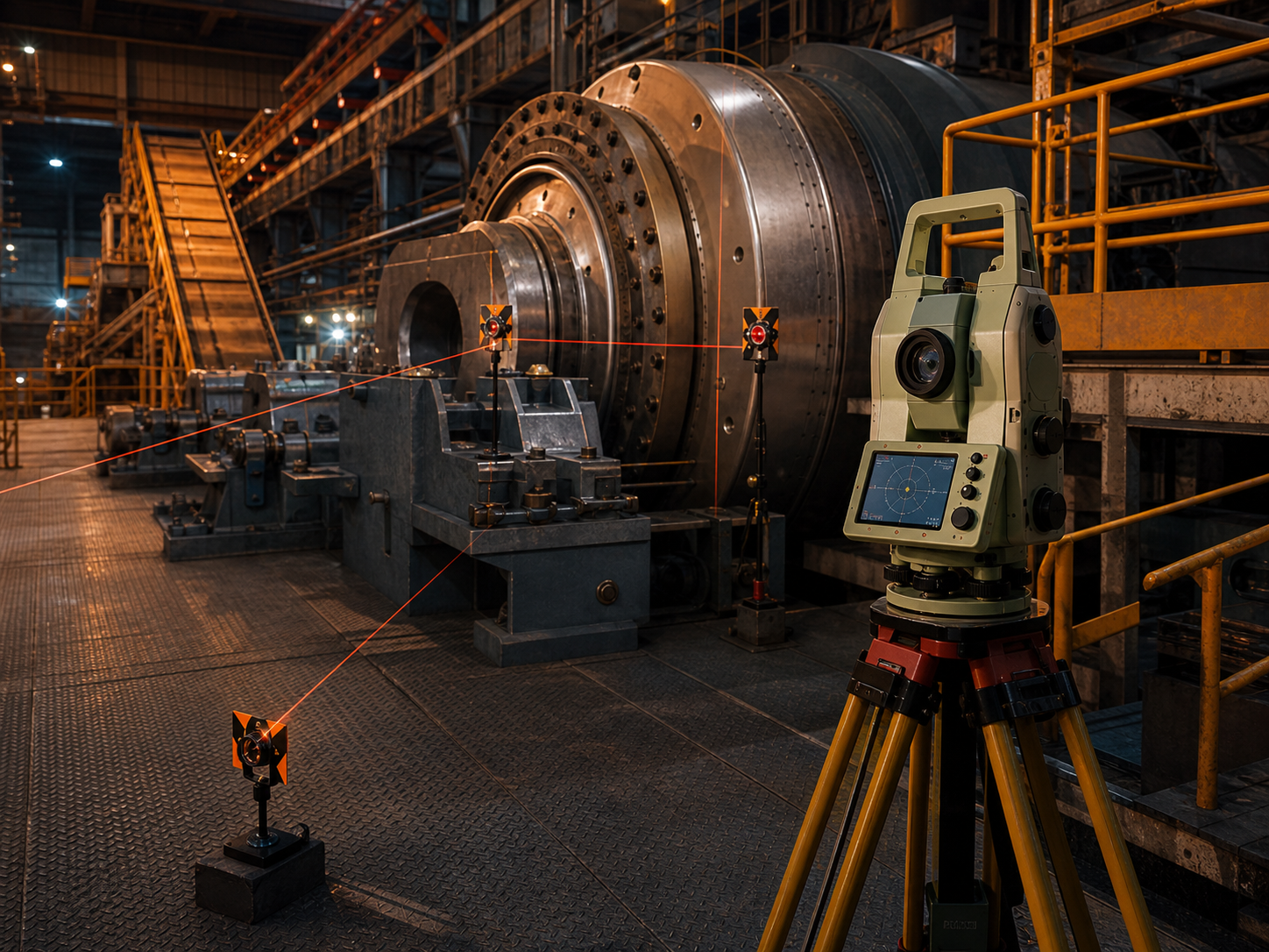
A mechanical alignment survey uses survey-grade instruments to measure the true geometry of rotating and load-bearing plant — mills, kilns, crane runways, conveyors, pumps and drive trains — then compares it against design so maintenance teams know exactly what to shim, move or re-machine. Done properly, it works to sub-millimetre tolerances, ties every reading to a stable local control network, and turns "the bearing keeps cooking" into a measured correction value. This guide covers the standards, equipment, tolerances, costs and a field-ready checklist so your next shutdown alignment runs to plan rather than to luck.
Key takeaways
- A defensible alignment survey is only as good as its control network — establish a stable local network adjusted by least squares to better than ±0.5 mm relative before you measure a single bearing.
- Typical working tolerances: equipment centrelines ±0.5–1.0 mm, crane rail span ±3 mm and elevation ±2 mm per 10 m (AS 1418.1 / AS 1418.18), conveyor idler lines ±3 mm, and monitoring to sub-millimetre with a Leica MS60 over multiple rounds.
- Instrument selection drives accuracy: a Leica MS60 MultiStation (0.5″, 1 mm + 1.5 ppm) for precision alignment and monitoring; a TS16 (1″, 2 mm + 2 ppm) for general dimensional control; an RTC360 (2 mm @ 10 m) or FARO Focus for as-built capture.
- Budget AUD $2,500–4,500 per crew per day; a standalone crane rail or conveyor survey runs $4,000–12,000, a rotary mill or kiln alignment $8,000–18,000 including analysis and a reporting deliverable.
- Cold versus hot matters — thermal growth on a kiln shell or a hot pump casing can shift a centreline 5–15 mm, so the survey method must account for operating-temperature deformation, not just the static reading.
- Tie everything to a known datum (GDA2020 / MGA2020 horizontal, AHD vertical) only where site coordinates are needed; for pure machine geometry a stable local frame is usually faster and tighter.
What a mechanical alignment survey actually measures
A misaligned ball mill at a copper concentrator in north-west Queensland was eating trunnion bearing inserts on a three-month cycle against a design life of well over a year. A precision alignment survey traced it to a 1.9 mm centreline rise across the discharge bearing — invisible to the maintenance crew, obvious to a total station tied to a stable network. The shim correction cost a fraction of one bearing change.
Mechanical alignment surveying sits between traditional surveying and engineering metrology. Where a land surveyor cares about boundaries and contours to the centimetre, an alignment surveyor cares about the rotation axis of a mill, the runway geometry of an overhead crane, or the straightness of a 2 km conveyor — to the millimetre or better. The deliverable is not a map; it is a set of deviation values, plots and adjustment recommendations a fitter can act on during the outage.
The core measurands across most mechanical work are:
- Centreline position — the true horizontal and vertical position of a rotation axis (mill, kiln, pump, fan, gearbox).
- Straightness — deviation of a line of bearings, idlers or rail from a best-fit line.
- Level and slope — longitudinal inclination and cross-level, critical for kilns and crane rails.
- Span and gauge — distance between paired elements such as crane runway rails.
- Flatness and verticality — for soleplates, baseframes and structural steel.
- Deformation over time — movement between survey epochs for monitoring programmes.
Key point: the value is in the comparison. A raw coordinate means nothing until it is referenced to design intent through a known control network and datum.
Standards and datums that apply in Australia
Alignment work is governed less by a single "alignment standard" and more by a stack of equipment, survey and safety standards. The ones that come up most on Australian sites:
| Reference | Scope | Relevance |
|---|---|---|
| AS 1418.1 / AS 1418.18 | Cranes, hoists and winches; crane runways | Runway rail tolerances, inspection intervals |
| ISO 1940 / ISO 21940 | Rotor balancing quality | Context for vibration that alignment can't fix |
| ISO 17123 series | Field procedures for testing survey instruments | Justifying instrument accuracy claims |
| ICSM SP1 | Standard for the Australian survey control network | Connecting machine surveys to national datum |
| GDA2020 / MGA2020 | National horizontal datum and map grid | Site coordinates where required |
| AHD | Australian Height Datum | Vertical referencing for level work |
| CASA CASR Part 101 | Remotely piloted aircraft operations | Mandatory for any UAV/drone capture component |
Two practical notes. First, for pure machine geometry you rarely need GDA2020 — a tight local frame is faster and avoids importing grid scale factor and ppm error into a job where you care about relative millimetres, not absolute position. Connect to MGA2020/AHD only when the client needs the asset coordinated against site infrastructure. Second, if any part of the scope uses a drone (for example, RGB or LiDAR capture of an inaccessible conveyor gantry), the operation must comply with CASA CASR Part 101 — operator accreditation or RePL, an ReOC where applicable, and approvals for controlled airspace common around ports and refineries.
Equipment and the accuracy it delivers
The instrument is the floor on your achievable tolerance — no amount of processing recovers precision the hardware never captured.
| Equipment | Role in alignment work | Accuracy |
|---|---|---|
| Leica MS60 MultiStation | Precision centrelines, monitoring, demanding alignment | 0.5″ angle; 1 mm + 1.5 ppm |
| Leica TS16 total station | General dimensional control and alignment | 1″ angle; 2 mm + 2 ppm |
| Trimble S-series total station | Equivalent general-purpose alignment | ~1″; 1 mm + 2 ppm |
| Leica RTC360 laser scanner | As-built capture, clash and clearance, ovality | ~2 mm @ 10 m |
| FARO Focus Premium scanner | As-built and structural capture | ~2 mm @ 10 m |
| Precision inclinometer | Roller and soleplate slope/tilt | ±10 arc-seconds |
| DJI M350 RTK + payload | Aerial capture of inaccessible structures | Task dependent; CASR Part 101 |
For sub-millimetre monitoring and tight centreline work, the MS60's angular precision and Automatic Target Recognition make it the default. For broad dimensional control and routine crane or conveyor surveys, the TS16 or a Trimble S-series is the workhorse. Laser scanning earns its place when you need full geometry — tyre ovality on a kiln, a clash check before a chute swap, or an as-built of a congested transfer tower — but for the actual rotation axis of a bearing, direct total station observation to a defined target remains more accurate and more directly traceable than fitting a surface to a point cloud.
The field method, step by step
- Plan and review. Pull equipment drawings, the previous alignment report, and maintenance history. Confirm the outage window, access (scaffold, EWP, confined space), and isolation requirements.
- Establish control. Install stable targets or pillars with clear intervisibility to every measurement station. Observe multiple rounds and run a least-squares adjustment — aim for relative accuracy better than ±0.5 mm. This network is the spatial backbone of the whole job.
- Reference design. Bring the design centreline, levels and tolerances into the same frame as the control network so comparison is direct, not arithmetic done later on a clipboard.
- Capture static geometry. Observe defined points — bearing centreline fittings, rail heads, idler frames, soleplates — typically 4–8 points per rotating element to compute a centre of rotation.
- Account for temperature. Note shell or casing temperature. Where the asset operates hot, either survey at representative temperature or apply documented thermal-growth allowances; a cold reading alone can mislead the adjustment.
- Analyse. Fit best-fit lines and axes, compute deviations against design, and convert them into shim and move values a fitter can apply directly.
- Verify after adjustment. Re-measure the corrected element. Adjustment is iterative — a move at one support shifts adjacent supports, so plan two to three correction-and-check cycles on complex assets.
- Report. Issue deviation tables, plots and recommendations with the instrument used, the network accuracy achieved, and the datum or local frame stated.
Watch out: never run alignment on construction-grade or consumer instruments. Sub-millimetre tolerances demand survey-grade gear with current calibration traceable to national standards under the ISO 17123 procedures.
Pre-survey field checklist
Hand this to the crew lead before mobilising. A clean checklist is the difference between a one-mobilisation job and an expensive second trip.
- Equipment GA drawings and design tolerances obtained
- Previous alignment report and baseline data located
- Outage window and access plan confirmed (scaffold / EWP / confined space permits)
- Isolation, lock-out/tag-out and site induction completed
- Stable control point locations identified with clear sightlines
- Instrument calibration certificates current and on site
- Operating temperature / thermal-growth approach agreed with the client
- Target fittings (centreline plugs, prisms) available and fitted
- Datum decision made: local frame vs GDA2020/MGA2020 + AHD
- If UAV capture in scope: CASR Part 101 approvals and airspace clearance confirmed
- Deliverable format and tolerance acceptance criteria agreed in writing
Tolerances and indicative costs
Tolerances are always subordinate to the manufacturer's specification — these are the typical working values Australian crews target when the spec is silent.
| Asset / parameter | Typical tolerance | Notes |
|---|---|---|
| Equipment rotation centreline | ±0.5–1.0 mm | Mills, pumps, fans, gearboxes |
| Kiln shell axis straightness | ±3–5 mm over full length | Allow 5–15 mm thermal bow when hot |
| Crane rail span | ±3 mm | AS 1418.1 guidance |
| Crane rail elevation | ±2 mm per 10 m | Longitudinal and cross-level |
| Conveyor idler line | ±3 mm | Straightness and level |
| Structural as-built | ±5 mm | Practical completion / handover |
| Deformation monitoring | sub-millimetre | MS60, multiple rounds, multi-epoch |
Costs depend on scope, location, access and schedule. Indicative AUD ranges for budgeting:
| Service | Indicative cost (AUD) | Typical duration |
|---|---|---|
| Crew day rate (instrument + surveyor) | $2,500–4,500 | per day |
| Crane rail survey | $4,000–9,000 | 1–3 days |
| Conveyor alignment | $5,000–12,000 | 2–5 days |
| Rotary mill or kiln alignment | $8,000–18,000 | 2–4 days + analysis |
| Laser scan as-built (plant area) | $4,000–15,000 | 1–5 days |
| Monitoring programme (per visit) | $1,500–3,000 | ongoing |
Remote mobilisation to the Pilbara, the Bowen Basin or Mount Isa, after-hours shutdown work, and confined-space or working-at-heights requirements all push the upper end. For the full service scope and what each deliverable includes, see our mechanical surveys overview.
Common problems a survey will catch
- Soft foot and base distortion — a frame that twists when bolts are torqued, masking the true centreline. A survey of the soleplate flatness exposes it before alignment is attempted.
- Thermal misreads — a pump aligned cold that goes out the moment it reaches operating temperature; the survey method has to plan for growth.
- Crane rail creep — span opening up or cross-level drifting over years of traffic, driving wheel flange wear and motor trips, picked up against AS 1418 tolerances.
- Conveyor belt drift — traced to idler frames out of square or a structure that has settled, not the belt itself.
- Foundation settlement — cumulative pier movement on kilns and large mills, only visible when each support is measured against a stable external network.
Most of these are invisible to inspection and obvious to measurement. That is the entire case for surveying: you cannot shim what you have not measured. Our mechanical surveys team builds the control network and reporting around exactly these failure modes.
Frequently asked questions
How often should we run an alignment survey?
For critical rotating equipment, verify alignment annually or after any significant event — bearing replacement, shell or section replacement, foundation work, or a near-by construction disturbance. High-duty assets (over roughly 8,000 operating hours a year) justify six-monthly checks. AS 1418.18 also drives periodic crane runway inspection; if your runways haven't been surveyed in three years, schedule one as routine maintenance.
What's the difference between a laser-tracker alignment and a total station survey?
Laser trackers excel at very small, high-density volumes — a single machine or assembly to a few thousandths of a millimetre. Total stations cover plant-scale geometry — a 100 m kiln, a full crane runway, a conveyor line — to sub-millimetre over far greater distances, tied to a site control network. For most heavy-industry alignment the total station (MS60/TS16 or Trimble S-series) is the right tool; trackers come in for confined precision assembly.
Do we need GDA2020 coordinates for a machine alignment?
Usually not. Pure machine geometry is best handled in a tight local frame, which avoids importing grid scale and ppm error into a relative-millimetre job. Connect to GDA2020/MGA2020 and AHD only when the client needs the asset coordinated against site infrastructure or other surveys.
Can a drone do part of an alignment survey?
A UAV such as a DJI M350 RTK is excellent for capturing inaccessible structure — high conveyor gantries, headframes, stacker geometry — feeding photogrammetry or LiDAR into the as-built. It does not replace direct measurement of a rotation axis. Any flight must comply with CASA CASR Part 101, including airspace approval, which matters around ports, refineries and regional airfields.
How long does a typical alignment survey take?
A crane rail or conveyor survey is generally one to three days on site. A rotary mill or kiln cold alignment is two to four days of field time plus analysis and reporting. Building the control network is front-loaded effort that pays back in data quality across the whole job — don't let it be the step that gets squeezed.
Talk to ISS
If you have a shutdown coming up, or an asset that keeps eating bearings, the cheapest move is to measure before you adjust. Industrial Spatial Solutions runs precision alignment surveys across Australian mining, processing, ports and manufacturing — from our base in the Illawarra to the Pilbara, the Bowen Basin and beyond — using Leica MS60, TS16 and RTC360 hardware, least-squares-adjusted control networks, and reports your fitters can act on the same shift. Call 0407 057 015 or contact us to scope your next mechanical alignment survey, or read more about our mechanical surveys capability.